Air University Review, March-April 1974
VISUALLY COUPLED SYSTEMS
Lieutenant Colonel Joseph A. Birt, USAF
Thomas A. Furness III
The capability to "look and shoot" was but a
fantasy in the days of the Flash Gordon and Buck Rogers comic strips. Soon today’s
Air Force pilot will be able to aim his weapons by a mere glance and fire along his line
of sight by the simple push of a button. Systematic research and development of
visual-coupling concepts, to improve man’s relationship with his machine, are helping
to bring a "look and shoot" capability closer to operational reality.
Recent combat experience has shown that many tactical, reconnaissance/strike, and
air-superiority systems are operator-limited by both the task loading placed on the crew
and the design of the interface between the operator and his machine. As long as tactical
weapon systems are used in a high-threat environment, the flight profiles necessary for
survivability will dictate that the operator perform all essential tasks effectively,
accurately, and, most important, expeditiously. A well-designed interface lets him use his
natural perceptual and motor abilities optimally. Such limiting factors especially
critical in weapon delivery missions where visual target acquisition and weapon aiming are
task requirements.
Since 1965, in an attempt to improve aircraft man-machine design, human-factors engineers
of the Aerospace Medical Research Laboratory (AMRL) at Wright-Patterson AFB, Ohio, (a unit
of Aerospace Medical Division) have been pioneering techniques to "visually
couple" the operator to his weapon system.
Visually Coupled Systems Concepts
A visually coupled system is more correctly a special subsystem that integrates
the natural visual and motor skills of an operator with the machine he is controlling. An
operator visually searches for, finds, and tracks an object of interest. His line of sight
is measured and used to aim sensors and/or weapons toward the object. Information related
to his visual/motor task from sensors, weapons, or central data sources is fed back
directly to his vision by special displays so as to enhance his task performance. In other
words, he looks at the target, and the sensors/weapons automatically point at the target.
Simultaneously with the display, he verifies where sensors/weapons are looking. He
visually fine-tunes their aim, and he shoots at what he sees.
Two functions are performed: a line-of-sight sensing/control function and a display
feedback function. Although each may be used separately, a fully visually coupled system
includes both. Thus, it is a unique control/display subsystem in which man’s line of
sight is measured and used for control, and visual information is fed back directly to his
eyes for his attention and use.
Currently a helmet-mounted sight is used to measure head position and line of sight. An
early version of a helmet sight was used in an in-flight evaluation at Tyndall AFB in
1969. Various experimental sights have undergone flight tests. The U.S. Navy has produced
a similar sight for operational use in F-4J and F-4B aircraft.
A helmet-mounted display is used to feed back information to the eye. An early bulky experimental display completely occluded outside vision to the right eye. Later versions permit a see-through capability, which allows simultaneous viewing of the display and the outside world scene. Many experimental display improvements are under study, but display flight-test experience is still limited. Research and development efforts are under way to reduce size, weight, and profile and to increase the performance of future visual coupling devices. Before looking at development progress toward operational reality, let’s explain in general terms how such sights, displays, and visually coupled systems are now mechanized and discuss their potential capabilities.
Helmet Sight Components And Capabilities
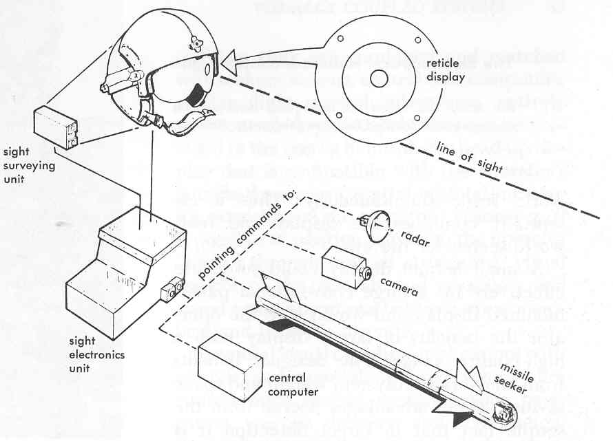
In the mid-sixties Honeywell selected, as one way to mechanize line-of-sight
determination, an electrooptical technique for determining helmet position and the line of
sight through a reticle. (Figure 1) Rotating parallel fanlike planes of infrared energy
from the sight surveying units (mounted on canopy rails) scan two photo diodes on the side
of the helmet. Timing signals from the scanners and diodes are processed by a digital
computer (sight electronics unit) to determine line of sight. Such line-of-sight
information can be used to point a variety of other subsystems.
A helmet-mounted sight facilitates wide off-boresight sensor or weapon aiming and speeds target acquisition. It permits continuous visual attention to the target outside the cockpit while sensors/weapons are slewed, and the hands are free from slewing control. The sight capitalizes on the ease and accuracy of the operator’s natural eye/head tracking abilities. His natural outside-the-cockpit spatial orientation is used throughout target acquisition.
Helmet Display Components And Capabilities
In an experimental helmet-mounted display video and symbolic signals are received from
various alternative aircraft subsystems. Cathode-ray tube (CRT) imagery is projected
directly to the eye of the operator in such a way that it appears to be focused upon
real-world background. A collimation lens performs the focus at infinity. The combiner
reflects the imagery into the eye much as a dental mirror does; however it permits the eye
to see through to the real-world scene simultaneously. Thus it essentially combines the
display and real-world scenes for the eye.
A small helmet display could substitute effectively for a large conventional panel-mounted
display and would give the operator the benefits of larger display with a high-quality
image. The designer benefits from an overall subsystem weight and space savings. These
advantages accrue from the simple fact that in target detection it is image size upon the
retina of the eye which counts. A one-inch-diameter CRT display presented as a virtual
imagel and placed one inch in front of the eye results in approximately the
same image size on the retina as a 21-inch CRT would mounted on a panel 21 inches away
from the eye.2 Miniature CRT technology can now provide sufficient resolution
to make a high-quality helmet-mounted image display practical.
Even though most aircraft panels cannot accommodate large CRT’s, it is important that
the displayed imagery be large enough to be detected and identified by the eye. In other
words, the image size detection capabilities of the sensor, the display, and the eye
should be made as compatible as possible. Helmet-mounted displays offer designers a new
way to achieve this compatibility. They offer the operator continuous head-up,
captive-attention viewing. When the display is used alone, selected sensor imagery, flight
control/display symbols, or other subsystem status information can be directly presented
to the eye no matter where the operator is looking. However, comprehensive analyses and
ground and in-flight evaluations of the operator’s capability to use the information
must be carried out if operator effectiveness is to be realized.
Visually Coupled Systems Components And Capabilities
The helmet-mounted sight and display are combined as a system integrated with the,
operator’s vision. Mechanization of the full system involves integration of the sight
and display components into a lightweight helmet development of a visor that automatically
varies light transmission to ensure appropriate display brightness contrast, and
improvements in the electronic and optic components.
When they are combined and matched with seekers, sensors, central data computers, and/or
flight control subsystems, entirely new control/display capabilities can be provided to
the user: a hemispheric head-up display that is compatible with the operator’s
outside-the-cockpit spatial orientation; sensor extensions of the operator’s vision
(e.g., it is possible to position sensors so the operator "looks" through
aircraft structures); visual control of the aircraft and weapons; and visual
communications between crew members and between aircraft.
Potential visual coupling applications with aircraft and remotely piloted vehicle fire
control, flight control, reconnaissance, navigation, weapon delivery, and communications
subsystems are many. In a night attack mission, for example, a low-light-level television
scene can be displayed, superimposed on the real world, off-boresight, and through
aircraft structure. Flight control and weapons data are provided in addition to the ground
scene on the display.
Visually coupled systems can also be used to input line-of-sight angle information into
central computers in order to update navigation; to identify a target location for
restrike, reconnaissance, or damage assessment; and to communicate coordinate locations in
real time with other aircraft or with command and control systems. By means of
intracockpit visual communication, one operator can cue another operator on where to look
for targets of interest. Similar nonverbal communication between forward air control and
attack aircraft is conceivable.
Development Progress
Visually coupled system development is merely highlighted here to give a glimpse
of progress. No attempt is made to be comprehensive but rather to give a feel for some of
the choices and changes that led to the current objectives of the Air Force engineering
development efforts. Until 1971 these efforts were mainly exploratory. Since March 1971,
the Aerospace Medical Research Laboratory has pursued exploratory development of advanced
concepts and engineering development of visual coupling devices. Progress to date
indicates that these devices will soon be ready for Air Force operational use.
Helmet-mounted Sight Development
Historically, it is not possible to trace the basic line-of-sight and display-feedback
concepts to specific originators. Some credit for the sighting concept should go to
behavioral scientists who in the late forties and early fifties were engrossed in
systematic analyses of pilot eye movements to determine instrument scan and visual search
patterns.3 Initial applied sighting efforts in government and industry
concerned the accuracy of head and eye tracking in the laboratory.4 It was
apparent that accuracy and effectiveness were functions of the head and/or eye position
sensing techniques. Applications had to await practical sensing technologies. Head
position tracking has received the most applied emphasis. Eye position tracking continues
to be explored. It was also evident that the proof for any sighting technique would be in
its accuracy and acceptability in flight.
The Army, Navy, Air Force, and industry have pursued complementary developments of
helmet-mounted sights. Two especially noteworthy early approaches to line-of-sight
sensing: a mechanical head-position sensing system by Sperry, Utah Division, and an
electrooptical helmet-position sensing system by Minneapolis Honeywell were developed to
the brassboard5 stages for testing in the 1965 through 1967 time period.
Sperry’s sight is a mechanically linked system where helmet position is determined in
a manner similar to the working of drafting-board arms. A reticle in front of the
operator’s eye fixes the line of sight in reference to the helmet and its mechanical
linkage. A magnetic attachment provides a quick disconnect capability.6 Under
Army contracts, Sperry’s mechanical head-position tracker was evaluated in UH-1 and
AH-1G helicopters, starting in 1967. Subsequent testing has led to a production contract
to use the mechanical helmet-mounted sight as a backup target acquisition aid on certain
Cobra helicopters. The Air Force pursued the mechanical sight approach in early AC-130
gunship aircraft.
In 1968 and 1969, the Army tested the Honeywell electrooptical head-position sensing
system for the Cheyenne program. (The principles of such an electrooptical system were
mentioned in the discussion of the helmet sight system.) This original Honeywell unit was
a first-generation helmet-mounted sight. In 1968 the Air Force sponsored a test of
air-to-ground navigation/reconnaissance using a similar unit to pinpoint targets.7
This test successfully used the sight for ground target coordinate determination in
low-altitude, high-speed flight. However, helmet weight and center of gravity were problem
areas.
The Air Force sponsored further development to reduce the size and bulk and to improve
components. The resulting second-generation sight was then loaned to the Navy for a
significant F-4B flight test at Point Mugu, California, in June 1969.8 Navy
test pilots concluded that it provided additional target acquisition capability under
dynamic high G air-to-air combat conditions. As a result of that and later tests,9
the Navy contracted through McDonnell Douglas, St. Louis, for a helmet sight capability,
called Visual Target Acquisition System, to direct radar and missile target acquisition in
certain F-4B and F-4J aircraft.
An improved second-generation sight was flight-tested at Tyndall AFB later in 1969 in
F-101 and F-106 aircraft. This important test quantitatively determined the accuracy of
this sight under high maneuvering acceleration and wide off-boresight aiming condition.10
In the early sights discussed so far, a reticle was projected onto a "granny
glass" (combining glass) suspended directly in front of the eye. In a subsequent
(1970) Air Force exploratory development, a substantial improvement was made by projecting
the reticle directly upon a parabolic helmet visor, thus eliminating any visual
obstructions by the suspended granny glass. An experimental version of the helmet-mounted
sight with a visor reticle projection was included in flight tests in 1972 by the Air
Force at Tyndall AFB and by the Navy in conjunction with its Visual Target Acquisition
System testing. The Navy is currently retrofitting the visor reticle into its operational
F-4J fleet.
Each helmet-sight version represents a development improvement to meet program and
flight-test schedules. A current flight-testable sight has the photo diode sensors and
visor-projected reticle in one lightweight unit attached to the helmet.
Air Force visual coupling research and development activities center around the Aerospace
Medical Research Laboratory’s Project 5973, "Development of Visual Coupling
Aids." These development activities catalyze and complement the programs of the
sister services and industrial agencies. The project’s objectives are to provide the
Air Force with design criteria and test information for current sight applications and for
future advanced helmet sight, helmet display, and visual coupling equipment. Existing
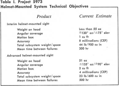
sights are ready for specific application evaluations. The project’s technical
objectives call for an interim helmet sight in 1974 and an advanced sight in 1976 (Table
I).11
In the latest sight under development, the sighting
mechanism is integrated into a lightweight helmet. This interim helmet unit will weigh
less than the standard 55-ounce Air Force helmet (HGU-2A/P). The advanced sight will
include one of three new advanced approaches12 to sensing head position and
likewise will be integrated, into a lightweight helmet. Flight-testing advanced
helmet-position sensing concepts in cooperation with the Navy is anticipated. An approach
by Polhemus Navigation Sciences, Inc., employs controlled projection and sensing of a
magnetic field. A Raytheon device uses light-emitting diodes on the helmet and
cockpit-mounted photo diode detection surfaces. A Honeywell technique employs ultrasonic
sound ranging and sensing.
Projected advanced sight improvements include enlarging from 1 cubic foot to 2 cubic feet
the head-motion envelope (motion box) within which helmet position can be determined. Also
sighting accuracy is to be improved, as is the effective coverage of line-of-sight azimuth
and elevation angles. Improvements will further reduce helmet weight to 51 ounces and will
reduce costs per unit while increasing its reliability. Helmet-mounted sight technology is
being integrated with helmet display developments (described below) to form the Air
Force’s fully visually coupled system.
Progress In Display And Visually Coupled
Systems
The helmet-mounted display concept has a long history and more diverse development
than the other sight concept. The idea of head-mounting a direct display to the eye
emerged concurrent (in the late fifties and early sixties) with the concept of
"head-up" windscreen displays in the Army-Navy Instrumentation Program (ANIP).
In 1963 Hughes Aircraft Company built an experimental head-mounted display. Earlier
efforts were deterred by CRT size and performance limitations as well as associated
human-factors problems.
Throughout visually coupled systems development, designers have been concerned, with
effects of such human-factor aspects as added weight to the helmet; brightness contrast
ratios between the display and the outside world scene; field of view (FOV);13
exit pupil size;14 display image quality; obstructions to peripheral vision;
display use under vibration; perceptual compatibility and conflict between the display
scene and the outside world scene; operator orientation when using a display; and display
scaling, dynamics, and content format. These problem areas will be addressed in achieving
current design objectives. Perceptual compatibility and display format also need to be
looked at in the context of each specific application.
In 1967 and 1968 a joint Air Force/Navy effort
flight-qualified a Hughes experimental helmet-mounted display. This display was monocular
and occluded outside vision in one eye. An improved see-through model was developed in
1970 and included a manually adjustable, variable light-transmission feature to regulate
ambient brightness experimentally. It had a 30° field of view.
There are currently three approaches to see-through display presentations. All involve
projection of a "virtual image" of the CRT face plate to the observer’s
eye. In one method, used in a 1969 Honeywell display, the image is projected onto a
combining glass, which is placed in the line of sight. It had only a 12.5° field of view.
The granny glass caused some visual obstruction. Subsequently, this technique has been
developed under Army contract to provide a 40° field of view.
When it became apparent that the projection of a sight reticle on a visor was going to be
successful, the same technique for display projection was explored by the Air Force on
contract with Honeywell. In 1972 they developed a flyable prototype with a rear-mounted
CRT and fiber optics image transmission from the rear across the top of the helmet to
front optical elements, which project it on the visor. Since this model included sight
provisions, it was the first USAF experimental visually coupled system. In this approach,
a special parabolic helmet visor is used as an optical element for presentation to the
eye. Although the visual interference of the granny glass is eliminated, only a narrow
20° field of view is possible.15
The third advanced approach to display projection
incorporates a holographic lens into a visor.16 Theoretically a holographic
display can achieve very wide fields of view, in excess of 60°. The technical feasibility
of this approach is still under study.
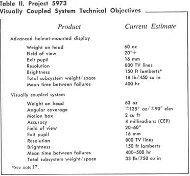
Project 5973 has established technical objectives for advanced helmet-mounted displays and
visually coupled systems to be achieved by 1977 (Table II). The advanced display and the
fully visually coupled system (VCS) will be integrated into lightweight helmets. They will
have resultant weights of 60 and 63 ounces, respectively. The field of view will be 20°
if a parabolic visor is used. If holographic technology permits, a larger field-of-view
capability will be incorporated. Efforts are under way to improve the quality of miniature
CRT devices by increasing display brightness17 while retaining their
resolution. In order to see a display projected on the visor under all conditions of
outside illumination, it will also be necessary to vary the light transmission
characteristics of the visor itself. Research is under way to develop a visor that
automatically varies its transmissivity with respect to ambient illumination, similar to
variable-density sunglasses.
The Future of Visually Coupled
Systems
Visually coupled systems are under Army consideration for night attack
applications in the Cobra helicopter and as a technology for future advanced attack
helicopters. The Navy is considering them for its AGILE and F-14 programs. The Air Force
is investigating potential applications for air-to-air and air-to-ground target
acquisition and weapon delivery, off-boresight weapon guidance, reconnaissance,
navigation, and remotely piloted vehicle control. Currently, the Air Force is conducting
or planning flight tests in conjunction with the AGM-65 Maverick, C-130 gunship, laser
designation systems, and weapons guidance developments.
The immediate future will be determined by progress made in current development and test
projects. Advanced technology will be transitioned into engineer development prototypes
for testing. Interim helmet-mounted sights will be ready for Air Force application testing
late in 1974, and advanced versions of sights, displays, and combined subsystems will be
ready in 1977.
The Aerospace Medical Research Laboratory is already looking beyond the technology discussed here to future visual coupling concepts that can further improve operator performance. One such line-of-sight sensing concept will determine eye position rather than head position. A display patterned after the human eye is also under study. These concepts are briefly discussed:
In summary, the "look and shoot" capability is around the corner. Systematic R&D pursuit of visual coupling technology is opening many possible applications. Development of components has progressed sufficiently that operational applications are feasible. Although helmet sighting technology is further along than helmet display, full visually coupled systems capabilities should be available to the Air Force in 1977. Operator and system performance will be appreciably enhanced by the application of visual coupling devices.
Aerospace Medical Division, AFSC
Notes
1. A "virtual image" in this context refers to the fact that the image which is reflected from the combiner or visor actually "appears" to be in focus and located in the outside world on the line of sight.
2. T. A. Furness III, "The Application of Helmet-Mounted Displays to Airborne Reconnaissance and Weapon Delivery," in Proceedings of First Symposium on Image Display and Recording, AFAL-TR-69-241, vol. I, U.S. Air Force Avionics Laboratory, Wright-Patterson AFB, Ohio, December 1969.
3. For early classical eye movement work see R. E. Jones, I. L. Milton, and P. M. Fitts, Eye Fixations of Aircraft Pilots I. A Review of Prior Eye Movement Studies and a Description of a Technique for Recording the Frequency, Duration and Sequences of Eye Fixations during Instrument Flight, Tech Report no. 5837 Air Materiel Command, Wright-Patterson AFB, Ohio, September 1949.
4. For example, see R. B. Lockard, and J. L. Fogard, (U) The Eye as a Control Mechanism, NOTS 1546, U.S. Naval Ordnance Test Station, China Lake, California, August 1956.
5. "Brassboard" stage refers to a flyable engineering model, which is beyond the stage of laboratory-workable "breadboard" models.
6. C. L. Keller, "Human Factors and Vipre Fire," Sperry Rand Corporation, Sperry Engineering Review, vol. 20, no. 2, 1967, pp. 17-23.
7. USAF Tactical Air Reconnaissance Center, (U) TACREACT, Tactical Air Command Test 67-118, TAC 7058-01054, Tactical Air Command/TARC, Shaw AFB, South Carolina, January 1968. (Report is CONFIDENTIAL.)
8. Department of the Navy, (U) First Partial Report on Project O/V63, Conduct an Operational Evaluation of the Helmet-Mounted Sight in an F-4 Aircraft as an Acquisition Aid during Air Combat Maneuvering, Command Operational Test and Evaluation Force, Norfolk, Virginia, October 1969. (Report is CONFIDENTIAL.)
9. Department of the Navy, (U) Conduct a Concurrent Technical and Operational Evaluation of the F-4 Dog Fight Optimization Systems, Final Report on Project C/V 20, Command Operational Test and Evaluation Force, Norfolk, Virginia, April 1972. (Report is CONFIDENTIAL.)
10. F. H. Dietz, Major, USAF, and J. D. Wise, Captain, USAF, (U) Final Report ADC/ADWC Project 69-19 Evaluation of the Helmet-Mounted Sight, Air Defense Weapons Center, 4750th Test Squadron, Tyndall AFB, Florida, December 1971. (Report is CONFIDENTIAL.)
11. From a Command Assessment Review of Project 5973, Visual Coupling Aids, presented by Colonel Fredric F. Doppelt, Commander, AMRL, at Hq Air Force Systems Command, 3 July 1973. Presentation information is available from the 6570th AMRL/HER, Wright-Patterson AFB, Ohio.
12. For comprehensive treatment of these new head-position sensing techniques see J. Kuipers, "The SPASYN—a New Transducing Technique for Visually Coupled Control Systems"; W. J. Haywood, Jr., "A New Electro-Optical Technique for Measuring Pilot Line of Sight in Aircraft Coordinates"; and R. T. Sawamura, "The Ultrasonic Advanced Helmet-Mounted Sight"—all in J. A. Birt, Lieutenant Colonel, USAF, and H. L. Task, editors, Proceedings of the Symposium on Visually Coupled Systems Development and Application, AMD TR 73-1, Aerospace Medical Division, Brooks AFB, Texas, 1973.
13. "Field of view" in this context refers to the angle which the image supplied by the display subtends at the eye.
14. The display’s "exit pupil" dimension is the diameter of the circular area within which the eye can move and still can see the displayed image. This dimension is measured at the entrance pupil of the eye. A large exit pupil is desirable in helmet-mounted displays so the image will not be lost under buffeting, turbulence, or high-acceleration conditions.
15. D. F. Kocian, Captain, USAF, and P. D. Pratt, "Development of a Helmet-Mounted Visor Display," in J. A. Birt, Lieutenant Colonel, USAF, and H. L. Task, editors, Proceedings of the Symposium on Visually Coupled Systems Development and Application, AMD TR 73-1, Aerospace Medical Division, Brooks AFB, Texas, September 1973.
16. For comprehensive technical papers on holographic optical elements for helmet-mounted displays see J. N. Latta, "Design of Holographic Element Systems for Helmet Displays," and D. G. McCauley, C. E. Simpson, W. J. Murbach, and H. W. Holloway, "Holographic Optical Elements for Helmet-Mounted Visual Head-Up Display," in J. A. Birt, Lieutenant Colonel, USAF and H. L. Task, editors Proceedings of the Symposium on Visually Coupled Systems Development and Application, AMD TR 73-1, Aerospace Medical Division, Brooks AFB, Texas, September 1973.
17. "Foot lambert" (in Table II) is a photometric measure of luminance or brightness. Efforts are under way to improve the quality of miniature CRT devices by increasing display brightness up to 500 foot lamberts while retaining 800 TV lines of resolution and 8-10 shades of gray presentation. A CRT brightness of 500 foot lamberts is desirable to give the specified 150 foot lamberts brightness on the visor display surface.
18. Recent papers dealing with sensing and using eye position in a VCS context include J. Merchant, R. Morrissette, and J. Porterfield, "Aerospace Medical Research Laboratory/Honeywell Remote Oculometer," and T. L. Coluccio and K. A. Mason, "The Viewing Hood Oculometer: A Sighting Control and Display Feedback System," both in J. A. Birt, Lieutenant Colonel, U and H. L. Task, editors, Proceedings of the Symposium on Visually Coupled Systems Development and Application, AMD TR 73-1, Aerospace Medical Division, Brooks AFB, Texas, September 1973.
19. Recent papers dealing with visually coupled dual field-of-view include J. B. Chatten, "Foveal Hat: A Head Aimed TV System with Foveal/Peripheral Image Format," and E. G. Schone, A. L. and Adamski Foote, "A Head Coupled TV for Remotely Manned Driving and Manipulation Tasks," both in J. A. Birt, Lieutenant Colonel, USAF, and H. L. Task, editors, Proceedings of the Symposium on Visually Coupled Systems Development and Application, AMD TR 73-1, Aerospace Medical Division, Brooks AFB, Texas, September 1973.
20. R. N. Winner, "A Color Helmet-Mounted Display System" in J.A. Birt, Lieutenant Colonel, USAF, and H. L. Task, editors, Proceedings of the Symposium on Visually Coupled Systems Development and Application, AMD TR 73-1, Aerospace Medical Division, Brooks AFB, Texas September l973.
Contributors
Lieutenant Colonel Joseph A. Birt (Ph.D., Purdue University) is Chief, Human Performance Division, Directorate of R&D, Aerospace Medical Division, Brooks, AFB, Texas. He has been a transport pilot in Air Defense Command and under AFIT earned graduate degrees in human factors and industrial psychology. As a human performance engineer at Wright-Patterson AFB, he was associated with the F-111 and B-1 programs. Colonel Birt has responsibility related to Aerospace Medical Research Laboratory’s human engineering, including visually coupled systems.
Thomas A. Furness III (B.S.E.E., Duke University) is a supervisory research engineer, Human Engineering Division, Aerospace Medical Research Laboratory, Wright-Patterson AFB. Commissioned in the Air Force in 1966, he pioneered research and development of helmet-mounted sights and displays. Mr. Furness is currently a manager of AMRL’s Project 5973 for visual coupling aids.
Disclaimer
The conclusions and opinions expressed in this document are those of the author cultivated in the freedom of expression, academic environment of Air University. They do not reflect the official position of the U.S. Government, Department of Defense, the United States Air Force or the Air University.
--------------------------------------------------------------------------------------------------------------------------------------------
Task and Kocian (1995) cite the U.S. Navy’s Visual Target Acquisition System (VTAS), developed in the 1960's, as the first fully operational visually coupled sighting system. [However, the system was abandoned due to lack of sufficient missile fire control technology.]
http://www.usaarl.army.mil/hmdbook/cp_001.htm
------------------------------------
12 December 1971 --Air Development Squadron Four (VX-4) reported on an extensive series of evaluations of the helmet mounted sight, the Visual Target Acquisition System, in the F-4 that had commenced in 1969. While the report cited a number of shortcomings, it concluded that the helmet sight was superior to operational equipment used by fighter pilots in air-to-air combat.
http://www.history.navy.mil/branches/avchr10.htm